Digital Terrain Modeling – Aspect models
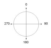 In digital terrain modeling the Aspect of a surface refers to the direction (azimuth) to which a slope face is orientated. The aspect or orientation of a slope can produce very significant influences on it, so it is important to know the aspect of the plane as well as the slope. Together the slope combined with the aspect of the surface can virtually define the surface plane completely in digital terrain modeling.
Aspect is measured in degrees (similar to a compass bearing) clockwise from magnetic north. A surface with 0 degrees Aspect would represent a north direction, an east facing slope would be 90 degrees, a south facing slope would be 180 degrees and a west facing slope would be 270 degrees.
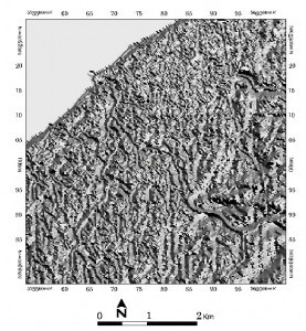
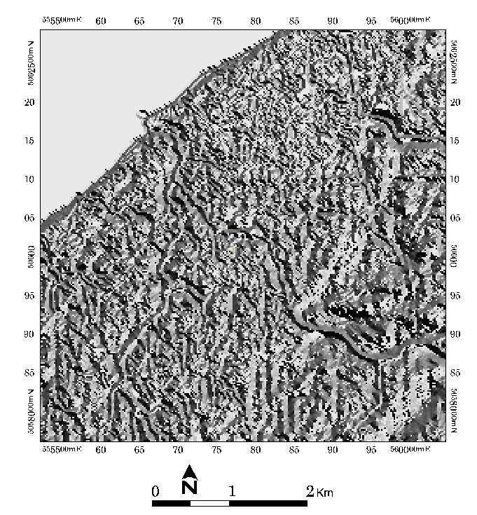
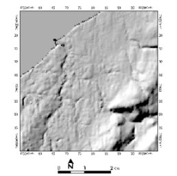
The example shown to the left (for larger image click here) is a raster aspect model of Lismore, Nova Scotia was derived from a digital elevation model (DEM) calculated using PCI Geomatica remote sensing software. It is represented with a grey scale color ramp and helps to indicate what direction slope faces are orientated.
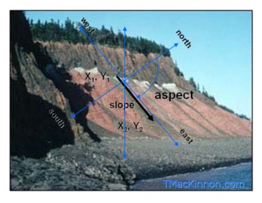
The image above is of an actual bedrock cliff with some technical information embedded onto the image to help better understand slope and aspect relationships. The black arrow represents the slope or the measured angle that the rock is dipping towards.
The aspect is the orientation that the arrow (slope) is pointing with respect to North, therefore the aspect for this slope would be in an easterly direction and often represented by 90 degrees. The blue arrows represent the X, Y and Z dimensions that the combination of both the slope and aspect would use to represent the terrain features.
